V carve inlays with Carbide Create v6

Carbide Create v7 has a v carve inlay toolpath feature added. But I don’t want to pay for v7 as I run my own home-grown CNC. Also Carbide dropped GCode output from v7 so… v6 it is…

So after much trial and error I’ve worked out how to get v6 to generate gcode for V Carve inlays.

Design Preparation

Clean up the vector nodes

Some fonts have overlapping sections. These need to be removed.

Select the text, go to the text tool and ‘Convert to Curves’

Then, with the text still selected perform a boolean union

NOTE: You can no longer edit the text – it is now just nodes and curves in Carbide

V Carving with Area Pocket Tool

The blue dotted lines represent the edges defined by the vectors. Multiple passes of the pocket and V bit may be necessary to clean out material to the desired depth.

For this example I am choosing a depth of 4mm

There is not always room to get the pocket bit in first. Where this happens Carbide Create will use the V bit which is less efficient and may need some manual clean up of wood fibres that hang on.

Left: Material removed by an end mill ; Right: V bit used to remove material. Note that the bottom of the V bit is not the same as the cut vector. Carbide calculates the offset based on depth of cut and the angle of the V bit.

Key to cutting plugs is the use of ‘Start Depth’ to get Carbide to cut beyond the vector line.

Machining the Socket (pocket?)

Use the ‘Advanced V Carve’ toolpath at the desired depth and ‘Enable Area Pocket Tool’

Don’t worry too much about how much of the cut is being done by the V Bit. Changing to a smaller pocket tool is better at getting into the corners but doesn’t yield much of a time saving as the bit runs more passes or runs slower. As the bottom of the socket is never seen I prefer a larger cutter that is less likely to break and pick out the fluff manually. 23 minutes for a 1/8″ end mill vs 21 minutes for 1/16″ end mill.

Machining the Plug

Copy the EXACT vectors used for the Socket

INVERT / FLIP THEM – Very important and easily forgotten

Create a 10mm offset vector around the inlay. You can go smaller but I like to cut my plug out on a bandsaw and a little extra wiggle room helps.

Delete unwanted vectors from the offset vector creation. They’ll stop the socket fitting properly

Machining the plug will require multiple passes. Select both the inlay vector & offset vector for each pass. We need to use the ‘Start Depth’ feature in order for Carbide to over-cut the vector lines so that the plug fits the socket. Going straight to the final pass will result in a very aggressive cut, probably chip out and a poor surface cut.

Plug shown in brown – this is what we want

A small gap at the bottom – space for any excess of glue and a little tolerance to ensure the plug can be pushed firmly into the socket without interference. Try 0.5mm

A larger gap at the top – again so there’s nothing getting in the way of pushing the plug home. Also space to cut off the excess material by hand or bandsaw should you choose not to cut it away on the CNC. Try 2mm

First Pass

Start Depth 0mm ; Cut depth 1.75mm – See middle step why 1.75mm is chosen

You will notice the V carve top edge is aligned to the vector lines in blue. If we cut full depth using only the first pass we will end up with a plug like this. Keep hammering I’m sure it’ll go

So… end of first pass looks like this. The green line is where we want to get to.

Middle Passes

Each pass uses the previous pass Max Depth as its ‘Start Depth’

Start Depth 1.75mm ; Cut depth 3.5mm

I’ve chosen 1.75 as the first cut so for the middle pass the depth can be 3.5mm – remember that small glue gap of 0.5mm? That is set by the final middle pass.

NOTE: For a 4mm socket only one middle pass is needed. Deeper sockets may require more than one middle pass. Just remember that the depth of the final middle pass should be your socket depth minus the glue gap.

Middle pass should look like below. Note the effect of the changing the Start Depth. The V bit is now beginning to cut beyond the vectors lines in blue.

Final Pass

As before Start Depth 3.5mm ; Cut depth 5.5mm

Adding an extra 2mm for the top clearance and we finally get our plug machined as below

All in one file (.c2d)

Using layers for the design and a toolpath group for sockets & plug allows for a single carbide file. Worth looking into but I’m not describing that here.

Enable/Disable visibility and groups works quite well. But a separate socket & plug file are also an option.
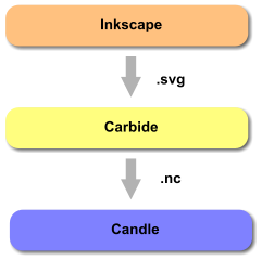
GCode

I use the GRBL or Basic GCode post processor for my home-made machine. I have no fancy tool changer – that’s all manual.

So, for me, the Carbide GCode is a real pain requiring multiple bit changes. So I developed a Tool Consolidator utility to parse the Carbide GCode and split it into separate files. One for each tool. It’s pretty simple – it looks for the M0 ;Txxx commands. Of course there’s some risk of aggressive cuts breaking bits etc as the cutting paths are essentially run out of sequence. No liability accepted – use at your own risk.

This is especially helpful for the multi-pass plugs. I run all the end mill operations first, then V bit.

I don’t think I have a virus but be sure to scan the files BEFORE running the exe.

How to use the consolidator. Firstly unzip the files – put them somewhere you’ll find them.

Then right click on a gcode file (.gcode or .nc) and click ‘Open With..’. Pick ‘Choose an app on your pc’ and select the ToolConsolidator.exe in the folder you unzipped to.

Windows remembers the exe after you’ve done it once. Go to open with and you’ll see the tool consolidator listed.

Once run the Tool Consolidator will create a new folder named the same as the source GCode file and write separate files for each tool used.

Txxx is the tool number and _1, _2 is the order that the tools appear in the source GCode.

Tool numbers can be seen in Carbide Create – make sure to load the right file for the tool in your machine

CNC Cutting – Tool chain

Method

Tools

Toolchain Steps

Generate Scaled Drawing – Inkscape

Link to INKSCAPE

Scaled drawings are required to set the path of the cutting tool. These drawings are vector drawings where the lines have distinct start points and end points defined by coordinates.

Inkscape can also define line thickness, line colour and fill colour but this information is not required by the next toolchain step (Carbide). The file type I use for Toolpath Generation is .svg (Scaled Vector Graphic).

You can also download vector graphics from the internet to use with your CNC machine. Link to a few websites where I’ve found some good drawings:

Toolpath Generation – Carbide

Link to CARBIDE

So, the vector drawing defines the shape you want to cut. It does not define the size of the cutter, feed rate, depth of cut or dimensions of the material you are machining.

Carbide allows all these parameters to be factored in. Each line can be selected individually and the toolpath defined in stages or all at once depending upon what you’re trying to do.

Carbide generates the G-Code required to tell your CNC machine how to move and cut. .nc files are then loaded into the next toolchain step (Candle).

Send to CNC Machine – Candle

Link to CANDLE

My 3018 Pro came with an offline controller where the .nc file generated in the previous toolchain step could be put onto a memory card. This allows the CNC machine to be used without connection to a computer. I’ve never used the offline controller so no further details provided.

My preferred method of driving the CNC machine is to stream the data from a pc/laptop. Out of the box the 3018 Pro G-Code can be streamed over USB. After updating to bluetooth this is now done wirelessly.

Candle supports either USB or Bluetooth methods although I do need to close and reopen Candle if the pc hibernates or connection is lost with bluetooth.

Adjusting Machine Configuration

A list of the GRBL machine configuration options are can be found on GitHub.

Use Candle or GRBLControl to read or write GRBL settings. (Any serial terminal program can do the same thing)

Type commands at the bottom of the console area.

$$ returns the GRBL configuration values as shown here

Example: Change the maximum X axis distance to 200mm. The original value shown is 280mm (See $130=280).

Change to 200mm by entering

$130=200

The controller board should remember these values once set.

3018 Pro GRBL v1.1h Configuration

These parameters seem to work well for both laser and milling operations.

See here for explanation of GRBL configuration

 $0=10
$1=25
$2=0
$3=0
$4=0
$5=1
$6=0
$10=19
$11=0.010
$12=0.002
$13=0
$20=0
$21=0
$22=1
$23=3
$24=50.000
$25=500.000
$26=250
$27=1.000
$30=1000
$31=0
$32=0
$100=400.000
$101=400.000
$102=400.000
$110=1000.000
$111=1000.000
$112=1000.000
$120=2000.000
$121=2000.000
$122=2000.000
$130=280.000
$131=170.000
$132=40.000

Updating Cronos CNC Controller Board firmware to GRBL 1.1h

Firstly make a note of your GRBL machine settings. My Settings

  1. Download the GRBL version you want to flash onto the controller board from GitHub. It is the ZIP file you will need.
  2. Unzip it and remember where you put it.
  3. Download the Arduino IDE and install it (if you haven’t already got it). You will need the Windows App, not the online web editor.
  4. Load the Arduino IDE, select in the menu at the top of the IDE:
    • Sketch > Include Library > Add .ZIP Library…
  5. Select the grbl folder (inside the unzipped folder next to doc and build) and ‘Open’
  6. The GRBL library should now be installed within the IDE. Within the IDE select from the menu:
    • File > Examples > grbl > grblUpload
      • grbl gets lost among the long list of examples – look carefully
  7. Plug in the USB to the controller board
  8. In the IDE select
    • Tools > Board: > Arduino Uno
    • Tools > Port > COM?
      • The COM port number varies. If you have more than one to choose from unplug the CNC controller board and see which port disappears – that’s the one you need when you plug it back in.
  9. [OPTIONAL] To tweak the firmware configuration go to:
    • Documents > Arduino > libraries > grbl
    • Load the config.h into a text editor (Notepad). There’s lots of options all quite well explained within the comments.
  10. Upload new firmware by clicking:
    • Sketch > Upload

Now check your GRBL configuration and adjust the values back to your preferences.

Cronos Controller Board

Similar to that supplied with the 3018 Pro from Mostics

The controller board supplied with my 3018 Pro appears to match the picture above with one exception – the circuit board is red.

This controller is supplied with GRBL 0.9 installed. The 3018 Pro is supplied with the necessary firmware flashing tools to return to 0.9 if you decide to update and it goes wrong.

I have since flashed the controller with GRBL 1.1h to allow use of position homing on X & Y axis. It was necessary to tweak the configuration of the GRBL firmware so took the opportunity to update at the same time. Happy to report, so far, that version 1.1h appears to be fully compatible with this controller board.

Adding End-Stop Switches

End-Stop Switch

After a number of positioning errors and the machine making some nasty noises trying to move beyond limits it was obvious the addition of limit switches would be a good investment.

These Limit Switches from Amazon are compatible with the Cronos Controller Board. The cables provided fit without alteration.

I may yet add a Z axis end-stop but for now I’ve added switches only to the X & Y axis. In order to get the controller board to properly home the X & Y axis the firmware on the controller will need to be re-flashed to allow it to only home X & Y. I took this as an opportunity to update to GRBL 1.1h.

The configuration changes to the firmware are as below and are located about 100 lines into the config.h file:


// Define the homing cycle patterns with bitmasks. The homing cycle first performs a search mode
// to quickly engage the limit switches, followed by a slower locate mode, and finished by a short
// pull-off motion to disengage the limit switches. The following HOMING_CYCLE_x defines are executed
// in order starting with suffix 0 and completes the homing routine for the specified-axes only. If
// an axis is omitted from the defines, it will not home, nor will the system update its position.
// Meaning that this allows for users with non-standard cartesian machines, such as a lathe (x then z,
// with no y), to configure the homing cycle behavior to their needs.
// NOTE: The homing cycle is designed to allow sharing of limit pins, if the axes are not in the same
// cycle, but this requires some pin settings changes in cpu_map.h file. For example, the default homing
// cycle can share the Z limit pin with either X or Y limit pins, since they are on different cycles.
// By sharing a pin, this frees up a precious IO pin for other purposes. In theory, all axes limit pins
// may be reduced to one pin, if all axes are homed with seperate cycles, or vice versa, all three axes
// on separate pin, but homed in one cycle. Also, it should be noted that the function of hard limits
// will not be affected by pin sharing.
// NOTE: Defaults are set for a traditional 3-axis CNC machine. Z-axis first to clear, followed by X & Y.
//#define HOMING_CYCLE_0 (1<<Z_AXIS)                // REQUIRED: First move Z to clear workspace.
//#define HOMING_CYCLE_1 ((1<<X_AXIS)|(1<<Y_AXIS))  // OPTIONAL: Then move X,Y at the same time.
// #define HOMING_CYCLE_2                         // OPTIONAL: Uncomment and add axes mask to enable

// NOTE: The following are two examples to setup homing for 2-axis machines.
// #define HOMING_CYCLE_0 ((1<<X_AXIS)|(1<<Y_AXIS))  // NOT COMPATIBLE WITH COREXY: Homes both X-Y in one cycle. 

#define HOMING_CYCLE_0 (1<<X_AXIS)  // COREXY COMPATIBLE: First home X
#define HOMING_CYCLE_1 (1<<Y_AXIS)  // COREXY COMPATIBLE: Then home Y

// Number of homing cycles performed after when the machine initially jogs to limit switches.
// This help in preventing overshoot and should improve repeatability. This value should be one or
// greater.
#define N_HOMING_LOCATE_CYCLE 1 // Integer (1-128)

// Enables single axis homing commands. $HX, $HY, and $HZ for X, Y, and Z-axis homing. The full homing 
// cycle is still invoked by the $H command. This is disabled by default. It's here only to address
// users that need to switch between a two-axis and three-axis machine. This is actually very rare.
// If you have a two-axis machine, DON'T USE THIS. Instead, just alter the homing cycle for two-axes.
// #define HOMING_SINGLE_AXIS_COMMANDS // Default disabled. Uncomment to enable.

// After homing, Grbl will set by default the entire machine space into negative space, as is typical
// for professional CNC machines, regardless of where the limit switches are located. Uncomment this
// define to force Grbl to always set the machine origin at the homed location despite switch orientation.
#define HOMING_FORCE_SET_ORIGIN // Uncomment to enable.

It may be possible to zero both X & Y simultaneously but I chose to zero each in turn. For my own preference I also enabled the HOMING_FORCE_SET_ORIGIN so that the machine coordinates are positive.

Limit switches were placed on the left of the X axis and back of the machine for Y axis. This allows the home position (0,0) to align with the bottom left of the work piece. There are limit switches available that have the switch mounted 90 degrees but, if careful, you can bend them round which is what I did for the Y axis. I used a bit of hot melt glue to mount them, not pretty but works perfectly.

GRBL settings will need adjusting to reverse direction of the switch sensors.

$5=1         Reverses the limit switch inputs
$22=1 Enables the homing function
$23=3 Reverses the homing direction of X & Y allowing (0,0) to correspond to bottom left of the CNC bed

Once zero is established you can then determine the maximum X & Y travel and configure that too.

$130=280.000       Maximum X travel
$131=170.000 Maximum Y travel
$132=40.000 Not important as Z axis does not home (40-45 is about right)

$20 can be used to set soft limits so the machine never exceeds your new found limits but I found this interfered with the Z axis so just turned it off. There is bound to be a solution but Candle shows the size of the cut anyway as a final check and during the generation of G-Code I now know the bed size. So far no axis crashes.

HC-05 Bluetooth Module

Purchased from Amazon

Upgrade the 3018 Pro to Bluetooth

This HC-05 module is compatible with the Controller Board. The Bluetooth socket on the board is a 4 pin and this HC-05 module has 6 pins. The two outer pins are not required, simply plug the central 4 pins into the controller board leaving one pin either end disconnected.

The back of the controller board pins are labelled. Double check they match those of the Bluetooth module. I fitted mine with the button on the Bluetooth module facing downward with the controller board oriented with stepper motor connections on the top.

NOTE: The HC-05 default configuration is 9600 Baud rate and controller board is 115200 Baud. Before plugging in the module it will need to be configured to match the controller board. This is not a trivial task. I used an Arduino nano for this and renamed the module to something more appropriate at the same time.

See here for how to set up an Arduino to program the HC-05 module

The AT command needed to set the module to 115200 baud (as required by the 3018 controller board) is:

AT+UART=115200,1,0

You might also choose to change the module name, for this use the command AT+NAME=3018Pro