Day 1
A few days later Busta was at full health and was taken to Woodys wildlife rescue. They expected to release him into the wild a few weeks later. Be kind to all blackbirds – it could be Busta
Day 1
A few days later Busta was at full health and was taken to Woodys wildlife rescue. They expected to release him into the wild a few weeks later. Be kind to all blackbirds – it could be Busta
Method
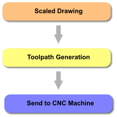
Tools
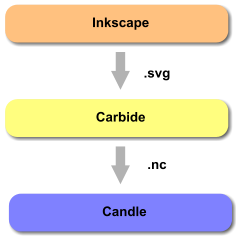
Link to INKSCAPE
Scaled drawings are required to set the path of the cutting tool. These drawings are vector drawings where the lines have distinct start points and end points defined by coordinates.
Inkscape can also define line thickness, line colour and fill colour but this information is not required by the next toolchain step (Carbide). The file type I use for Toolpath Generation is .svg (Scaled Vector Graphic).
You can also download vector graphics from the internet to use with your CNC machine. Link to a few websites where I’ve found some good drawings:
![]()
Link to CARBIDE
So, the vector drawing defines the shape you want to cut. It does not define the size of the cutter, feed rate, depth of cut or dimensions of the material you are machining.
Carbide allows all these parameters to be factored in. Each line can be selected individually and the toolpath defined in stages or all at once depending upon what you’re trying to do.
Carbide generates the G-Code required to tell your CNC machine how to move and cut. .nc files are then loaded into the next toolchain step (Candle).
![]()
Link to CANDLE
My 3018 Pro came with an offline controller where the .nc file generated in the previous toolchain step could be put onto a memory card. This allows the CNC machine to be used without connection to a computer. I’ve never used the offline controller so no further details provided.
My preferred method of driving the CNC machine is to stream the data from a pc/laptop. Out of the box the 3018 Pro G-Code can be streamed over USB. After updating to bluetooth this is now done wirelessly.
Candle supports either USB or Bluetooth methods although I do need to close and reopen Candle if the pc hibernates or connection is lost with bluetooth.
My 3018 Pro was supplied with GRBLControl. This software is used to send instructions to the CNC machine. These instructions are known as G-Code.
If you choose to update your CNC Controller board firmware to 1.1 you will be able to use the latest version of this software called ‘Candle’. It is free and downloadable at GitHub.
A list of the GRBL machine configuration options are can be found on GitHub.
Use Candle or GRBLControl to read or write GRBL settings. (Any serial terminal program can do the same thing)
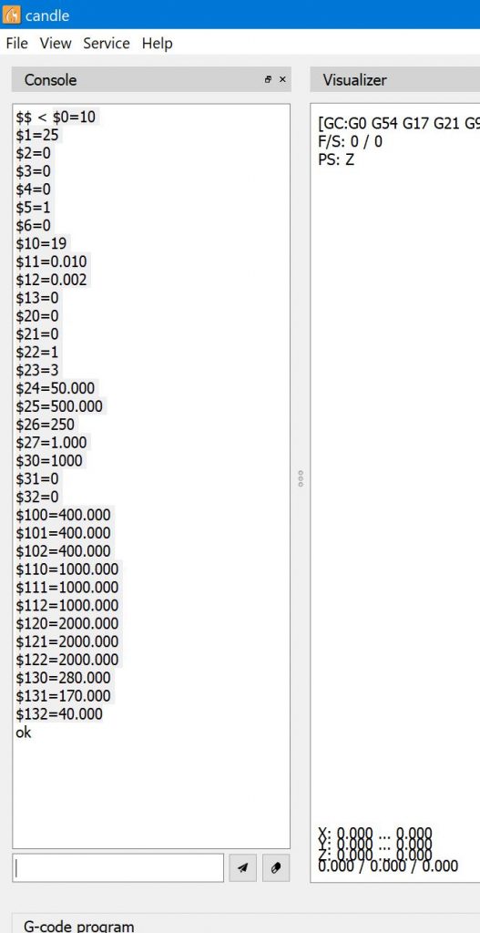
Type commands at the bottom of the console area.
$$ returns the GRBL configuration values as shown here
Example: Change the maximum X axis distance to 200mm. The original value shown is 280mm (See $130=280).
Change to 200mm by entering
$130=200
The controller board should remember these values once set.
These parameters seem to work well for both laser and milling operations.
See here for explanation of GRBL configuration
 $0=10
 $1=25
 $2=0
 $3=0
 $4=0
 $5=1
 $6=0
 $10=19
 $11=0.010
 $12=0.002
 $13=0
 $20=0
 $21=0
 $22=1
 $23=3
 $24=50.000
 $25=500.000
 $26=250
 $27=1.000
 $30=1000
 $31=0
 $32=0
 $100=400.000
 $101=400.000
 $102=400.000
 $110=1000.000
 $111=1000.000
 $112=1000.000
 $120=2000.000
 $121=2000.000
 $122=2000.000
 $130=280.000
 $131=170.000
 $132=40.000
Firstly make a note of your GRBL machine settings. My Settings
Now check your GRBL configuration and adjust the values back to your preferences.
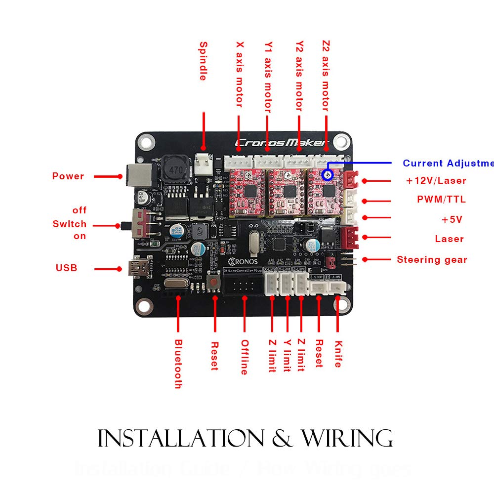
The controller board supplied with my 3018 Pro appears to match the picture above with one exception – the circuit board is red.
This controller is supplied with GRBL 0.9 installed. The 3018 Pro is supplied with the necessary firmware flashing tools to return to 0.9 if you decide to update and it goes wrong.
I have since flashed the controller with GRBL 1.1h to allow use of position homing on X & Y axis. It was necessary to tweak the configuration of the GRBL firmware so took the opportunity to update at the same time. Happy to report, so far, that version 1.1h appears to be fully compatible with this controller board.
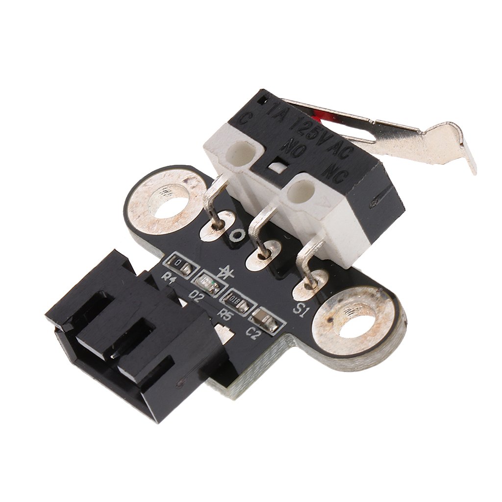
After a number of positioning errors and the machine making some nasty noises trying to move beyond limits it was obvious the addition of limit switches would be a good investment.
These Limit Switches from Amazon are compatible with the Cronos Controller Board. The cables provided fit without alteration.
I may yet add a Z axis end-stop but for now I’ve added switches only to the X & Y axis. In order to get the controller board to properly home the X & Y axis the firmware on the controller will need to be re-flashed to allow it to only home X & Y. I took this as an opportunity to update to GRBL 1.1h.
The configuration changes to the firmware are as below and are located about 100 lines into the config.h file:
// Define the homing cycle patterns with bitmasks. The homing cycle first performs a search mode
// to quickly engage the limit switches, followed by a slower locate mode, and finished by a short
// pull-off motion to disengage the limit switches. The following HOMING_CYCLE_x defines are executed
// in order starting with suffix 0 and completes the homing routine for the specified-axes only. If
// an axis is omitted from the defines, it will not home, nor will the system update its position.
// Meaning that this allows for users with non-standard cartesian machines, such as a lathe (x then z,
// with no y), to configure the homing cycle behavior to their needs.
// NOTE: The homing cycle is designed to allow sharing of limit pins, if the axes are not in the same
// cycle, but this requires some pin settings changes in cpu_map.h file. For example, the default homing
// cycle can share the Z limit pin with either X or Y limit pins, since they are on different cycles.
// By sharing a pin, this frees up a precious IO pin for other purposes. In theory, all axes limit pins
// may be reduced to one pin, if all axes are homed with seperate cycles, or vice versa, all three axes
// on separate pin, but homed in one cycle. Also, it should be noted that the function of hard limits
// will not be affected by pin sharing.
// NOTE: Defaults are set for a traditional 3-axis CNC machine. Z-axis first to clear, followed by X & Y.
//#define HOMING_CYCLE_0 (1<<Z_AXIS)                // REQUIRED: First move Z to clear workspace.
//#define HOMING_CYCLE_1 ((1<<X_AXIS)|(1<<Y_AXIS))  // OPTIONAL: Then move X,Y at the same time.
// #define HOMING_CYCLE_2                         // OPTIONAL: Uncomment and add axes mask to enable

// NOTE: The following are two examples to setup homing for 2-axis machines.
// #define HOMING_CYCLE_0 ((1<<X_AXIS)|(1<<Y_AXIS))  // NOT COMPATIBLE WITH COREXY: Homes both X-Y in one cycle.

#define HOMING_CYCLE_0 (1<<X_AXIS)  // COREXY COMPATIBLE: First home X
#define HOMING_CYCLE_1 (1<<Y_AXIS)  // COREXY COMPATIBLE: Then home Y

// Number of homing cycles performed after when the machine initially jogs to limit switches.
// This help in preventing overshoot and should improve repeatability. This value should be one or
// greater.
#define N_HOMING_LOCATE_CYCLE 1 // Integer (1-128)

// Enables single axis homing commands. $HX, $HY, and $HZ for X, Y, and Z-axis homing. The full homing
// cycle is still invoked by the $H command. This is disabled by default. It's here only to address
// users that need to switch between a two-axis and three-axis machine. This is actually very rare.
// If you have a two-axis machine, DON'T USE THIS. Instead, just alter the homing cycle for two-axes.
// #define HOMING_SINGLE_AXIS_COMMANDS // Default disabled. Uncomment to enable.

// After homing, Grbl will set by default the entire machine space into negative space, as is typical
// for professional CNC machines, regardless of where the limit switches are located. Uncomment this
// define to force Grbl to always set the machine origin at the homed location despite switch orientation.
#define HOMING_FORCE_SET_ORIGIN // Uncomment to enable.
It may be possible to zero both X & Y simultaneously but I chose to zero each in turn. For my own preference I also enabled the HOMING_FORCE_SET_ORIGIN so that the machine coordinates are positive.
Limit switches were placed on the left of the X axis and back of the machine for Y axis. This allows the home position (0,0) to align with the bottom left of the work piece. There are limit switches available that have the switch mounted 90 degrees but, if careful, you can bend them round which is what I did for the Y axis. I used a bit of hot melt glue to mount them, not pretty but works perfectly.
GRBL settings will need adjusting to reverse direction of the switch sensors.
$5=1         Reverses the limit switch inputs
$22=1       Enables the homing function
$23=3       Reverses the homing direction of X & Y allowing (0,0) to correspond to bottom left of the CNC bed
Once zero is established you can then determine the maximum X & Y travel and configure that too.
$130=280.000       Maximum X travel
$131=170.000       Maximum Y travel
$132=40.000         Not important as Z axis does not home (40-45 is about right)
$20 can be used to set soft limits so the machine never exceeds your new found limits but I found this interfered with the Z axis so just turned it off. There is bound to be a solution but Candle shows the size of the cut anyway as a final check and during the generation of G-Code I now know the bed size. So far no axis crashes.

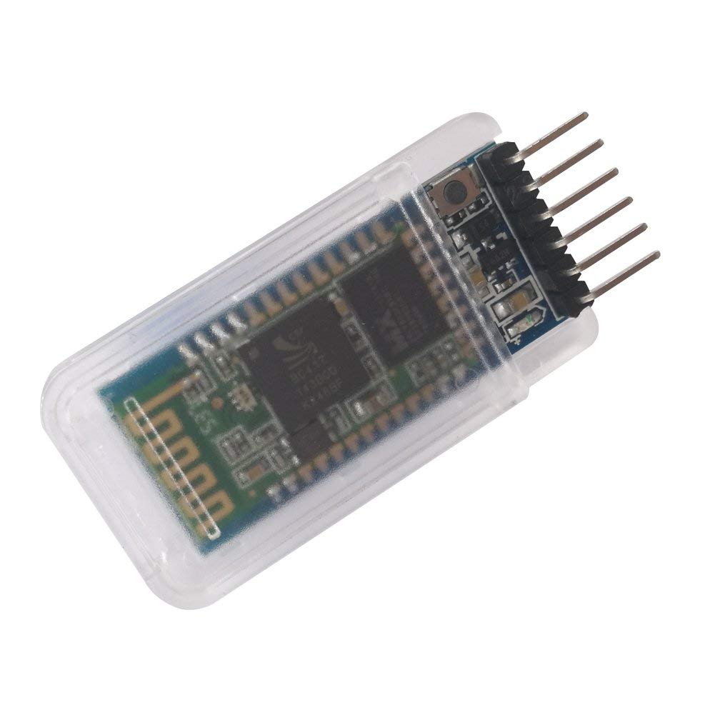
This HC-05 module is compatible with the Controller Board. The Bluetooth socket on the board is a 4 pin and this HC-05 module has 6 pins. The two outer pins are not required, simply plug the central 4 pins into the controller board leaving one pin either end disconnected.
The back of the controller board pins are labelled. Double check they match those of the Bluetooth module. I fitted mine with the button on the Bluetooth module facing downward with the controller board oriented with stepper motor connections on the top.
NOTE: The HC-05 default configuration is 9600 Baud rate and controller board is 115200 Baud. Before plugging in the module it will need to be configured to match the controller board. This is not a trivial task. I used an Arduino nano for this and renamed the module to something more appropriate at the same time.
See here for how to set up an Arduino to program the HC-05 module
The AT command needed to set the module to 115200 baud (as required by the 3018 controller board) is:
AT+UART=115200,1,0
You might also choose to change the module name, for this use the command AT+NAME=3018Pro